Overview:
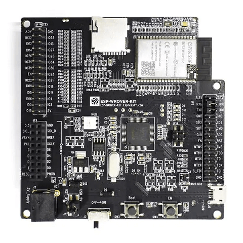
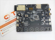
- The ESP-WROVER-KIT is a development board built around the ESP32 and produced by Espressif.
- This board is compatible with multiple ESP32 modules, including the ESP32-WROOM-32, ESP32-WROVER and ESP32-WROVER-B.
- The ESP-WROVER-KIT features support for an LCD and a MicroSD card. The I/O pins have been broken out from the ESP32 module for easy extension.
- The board carries an advanced multi-protocol USB bridge (the FTDI FT2232HL), enabling developers to use JTAG directly to debug the ESP32 through the USB interface.
- The development board makes secondary development easy and cost-effective.
Parameters:
| Manufacturer |
Espressif |
| Product Category |
Wifi Development Tools |
| Product |
Development Kits |
| Protocol Supported |
802.11 b/g/n |
| Tool Is For Evaluation Of |
ESP32 |
| Operating Supply Voltage |
5V |
| Datasheet |
ESP-WROVER-KIT V4.1
|
Block Diagram:

Board Layout Front:
Board Layout Back:
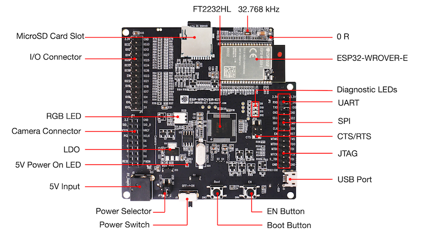
An external precision 32.768 kHz crystal oscillator provides a low-power consumption clock used during Deep-Sleep mode.
The FT2232 chip is a multi-protocol USB-to-serial bridge. Users can control and program the FT2232 chip through the USB interface to establish communication with ESP32.
This version of ESP-WROVER-KIT board has ESP-WROVER-B module installed that integrates 64-Mbit PSRAM for flexible extended storage and data processing capabilities.
Four red LEDs connected to GPIO pins of the FT2232 chip. Intended for future use.
The serial TX/RX signals on the FT2232HL and the ESP32 are broken out to each side of JP2.
SPI interface used by ESP32 to access flash and PSRAM memories inside the module.
Serial port flow control signals: the pins are not connected to the circuitry by default. To enable them, respective pins of JP14 must be shorted with jumpers.
JTAG interface: the JTAG signals on FT2232HL and ESP32 are broken out to the two sides of JP2. By default, the two signals are disconnected.
USB interface. It functions as the power supply for the board and the communication interface between PC and ESP32 module.
Reset button: pressing this button resets the system.
Download button: holding down the Boot button and pressing the EN button initiates the firmware download mode. Then user can download firmware through the serial port.
Power on/off button: toggling to the right powers the board on; toggling to the led & powers the board off.
Power supply seleclection interface: the ESP-WROVER-KIT can be powered through the USB interface or the 5V Input interface.
The 5V power supply interface is used as a backup power supply in case of fullload operation.
This red LED indicates that a power supply (either from USB or 5V Input) is applied to the board.
NCP1117(1A). 5V-to-3.3V LDO.
Camera interface: a standard OV7670 camera module is supported.
Red, green and blue (RGB) light emitting diodes (LEDs), which may be controlled by pulse width modulation (PWM).
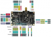
All the pins on the ESP32 module are led out to the pin headers on the ESPWROVER-KIT. Users can program ESP32 to enable multiple functions such as PWM, ADC, DAC, I2C, I2S, SPI, etc.
Develop applications that access Micro SD card for data storage and retrieval.
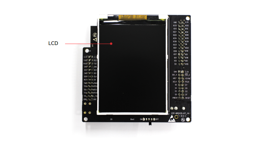
ESP-WROVER-KIT supports mountung and interfacing a 3.2” SPI (standard 4-wire Serial Peripheral Interface) LCD.
References:

 Sản phẩm phần cứng+
 Cảm biến - Module+
 Vi Điều Khiển - FPGA - SoC+
 Vi mạch tích hợp+
 Wireless - IoT+
 Phụ kiện Điện tử+
 Linh kiện cơ bản+
 Dụng cụ - Vật tư+
 Linh kiện ứng dụng+
 Tài khoản
