ESP32-Ethernet-Kit |
|||||||
|
|||||||
|
Thương hiệu:
Loại hàng:
TQ sản xuất
- Hàng chưa qua sử dụng do Trung Quốc sản xuất. - Hình thức: Mới - Chất lượng: Có thể kém hơn hàng do chính hãng sản xuất - Bảo hành: Không (nên kiểm tra với đơn mẫu) |
|||||||
|
|||||||
|
|||||||
|
|||||||
Thông tin sản phẩm
Overview:
Parameters:
| Product Category | Ethernet Development Tools |
| Product | Development Kits |
| Type | Ethernet Transceivers |
| Tool Is For Evaluation Of | ESP32-WROVER-B |
| For use with | ESP32 |
| Moisture Sensitive | Yes |
| Datasheet | ESP32-Ethernet-Kit |
Features:
Block Diagram:

Four female header pins for mounting this board onto Ethernet Board A.
Optional power supply to the PoE Board B.
Funtional Block Diagram:

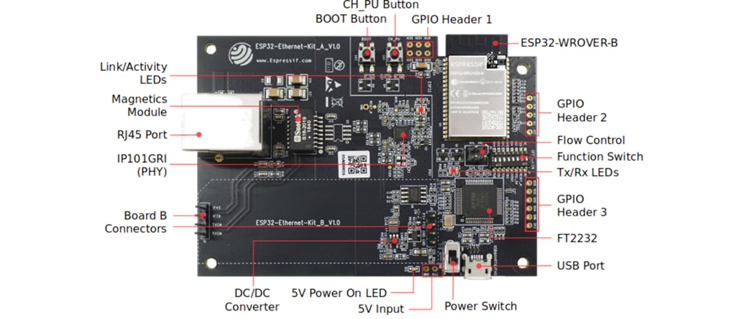
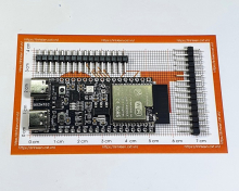
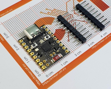
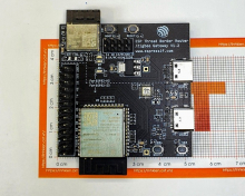
Board Layout:
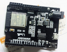
This ESP32 module features 64-Mbit PSRAM for flexible extended storage and data processing capabilities.
Five unpopulated through-hole solder pads to provide access to selected GPIOs of ESP32.
Jumper header with access to the board signals.
DIP switch used to configure the functionality of selected GPIOs of ESP32.
Two LEDs to show the status of UART transmission.
Provides access to some GPIOs of ESP32 that can be used depending on the position of the Function Switch.
Multi-protocol USB-to-serial bridge, which can be programmed and controlled via USB to provide communication with ESP32. Includes USB-to-JTAG interface on channel A and USB-to-serial on channel B.
USB interface. Power supply for the board as well as the communication interface between a computer and the board.
Power On/Off Switch. Toggling toward the Boot button powers the board on, toggling away from Boot powers the board off.
External 5V power supply for autonomously board operation.
Indicates power being supplied to the board from either a USB or 5V input.
Provides DC 5V to 3.3V conversion with output current up to 2A.
Header pins for mounting the PoE Board B.
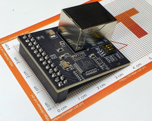
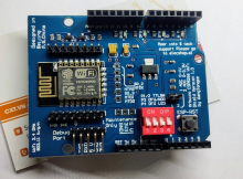
The Physical Layer (PHY) connection to the Ethernet cable is implemented using the IP101GRI chip. The connection between PHY and ESP32 is done through the reduced media-independent interface (RMII), a variant of the media-independent interface (MII) standard. The PHY supports the IEEE 802.3 / 802.3u standard of 10/100Mbps.
Ethernet network data transmission port.
The Magnetics are part of the Ethernet specification to protect against faults and transients, including rejection of common mode signals between the transceiver IC and the cable. The magnetics also provide galvanic isolation between the transceiver and the Ethernet device.
Two LEDs (green and red) that respectively indicate the "Link" and "Activity" statuses of the PHY.
Download button initiates Firmware Download mode for downloading firmware through the serial port.
Reset button.
This header provides six unpopulated through-hole solder pads connected to spare GPIOs of ESP32.
References:
Sản phẩm liên quan
Bán lẻ: 155,000₫
Bán lẻ: 170,000₫
Bán lẻ: 175,000₫
Bán lẻ: 410,000₫
Bán lẻ: 460,000₫
Bán lẻ: 60,000₫
Bán lẻ: 156,000₫
Bán lẻ: 105,000₫
Bán lẻ: 87,000₫
Bán lẻ: 450,000₫
Bán lẻ: 85,000₫
Bán lẻ: 120,000₫
Bán lẻ: 100,000₫
Bán lẻ: 143,000₫
Bán lẻ: 140,000₫
Bán lẻ: 150,000₫
Bán lẻ: 105,000₫
Bán lẻ: 150,000₫
Bán lẻ: 98,000₫
Đóng
Khách hàng của chúng tôi


ĐỐI TÁC CỦA CHÚNG TÔI


Số 110 Lô C2, Phố Nguyễn Cảnh Dị, Đại Kim, Hoàng Mai, Hà Nội
Điện thoại: 0243 200 1415 - Email: contact@cxt.vn
Thời gian làm việc: Từ 8g00 đến 17g30 [T2-T7]
0343 75 2012
085 811 2018
0965 626 239

Bản quyền © 2013 thuộc về CXT.VN

 Tài khoản
 Sản phẩm phần cứng