Overview:
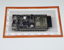
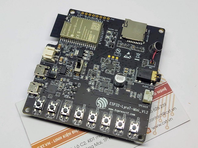
The ESP32-LyraT-Mini is an audio development board produced by Espressif built around ESP32. It is intended for audio applications, by providing hardware for audio processing and additional RAM on top of what is already on-board of the ESP32 chip. The specific hardware includes:
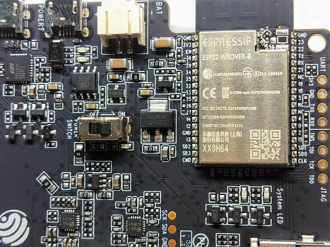
- ESP32-WROVER-B module
- Audio codec chip
- ADC chip
- Microphone on board
- Audio output
- 1 x 3-watt speaker output
- MicroSD card slot (1 line)
- Eight keys
- Two system LEDs
- JTAG and UART test points
- Integrated USB-UART Bridge Chip
- Li-ion Battery-Charge Management
Parameters:
| Manufacturer |
Espressif |
| Product Category |
Audio IC Development Tools |
| Product |
Development Boards |
| Type |
Audio |
| Tool Is For Evaluation Of |
ESP32-WROVER |
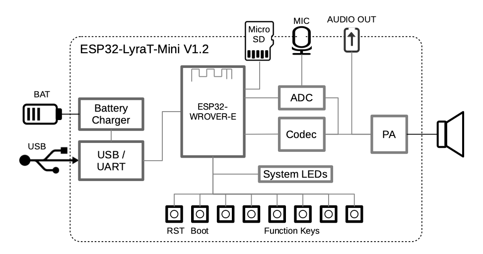
The block diagram below presents main components of the ESP32-LyraT-Mini and interconnections between components.
Board Details:
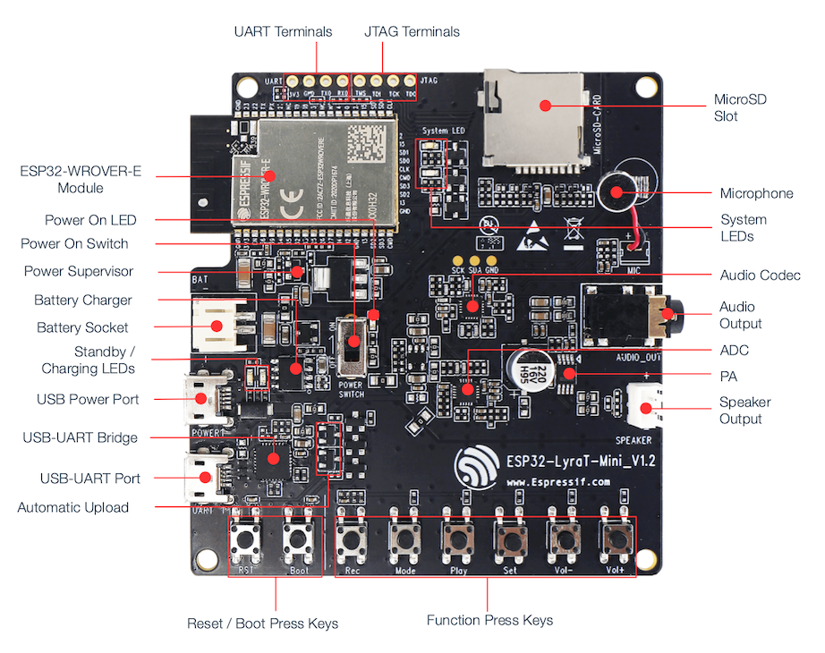
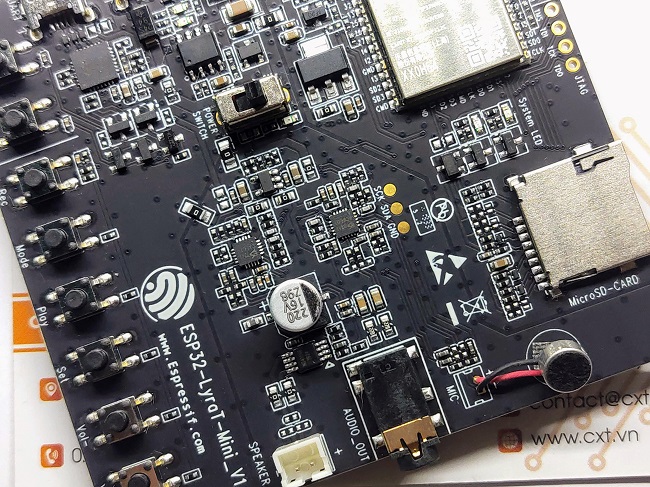
- MicroSD Card:
- The development board supports a MicroSD card in SPI/1-bit modes, and can store or play audio files in the MicroSD card. See MicroSD Card for pinout details.
- Microphone:
- On-board microphone connected to AINRP/AINRP of the Audio ADC Chip.
- System LEDs:
- Two general purpose LEDs (green and red) controlled by ESP32-WROVER-B Module to indicate certain operation states of the audio application using dedicated API.
- Audio Codec Chip:
- The audio codec chip, ES8311, is a low power mono audio codec. It consists of 1-channel ADC, 1-channel DAC, low noise pre-amplifier, headphone driver, digital sound effects, analog mixing and gain functions. It is interfaced with ESP32-WROVER-B Module over I2S and I2C buses to provide audio processing in hardware independently from the audio application.
- Audio Output:
- Output socket to connect headphones with a 3.5 mm stereo jack. One of the socket’s terminals is wired to ESP32 to provide jack insertion detection.
- Audio ADC Chip:
- The audio codec chip, ES7243, is a low power multi-bit delta-sigma audio ADC and DAC. In this board this chip is used as the microphone interface.
- PA Chip:
- A power amplifier used to amplify the audio signal from the Audio Codec Chip for driving the 4-ohm speaker.
- Speaker Output:
- Output socket to connect 4 ohm speaker. The pins have a standard 2.54 mm / 0.1” pitch.
- Audio Function Press Keys:
- Six press keys labeled Rec, Mode, Play, Set, Vol- and Vol+. They are routed to ESP32-WROVER-B Module and intended for development and testing of a UI for audio applications using dedicated API.
- Boot/Reset Press Keys:
- Boot: holding down the Boot button and momentarily pressing the Reset button initiates the firmware upload mode. Then user can upload firmware through the serial port. Reset: pressing this button alone resets the system.
- Automatic Upload:
- A simple two transistor circuit to put ESP32 into firmware upload mode depending on the status of UART DTR and RTS signals. The signals are controlled by an external application to upload the firmware over the USB-UART interface.
- USB-UART Port:
- Functions as the communication interface between a PC and the ESP32 module.
- USB-UART Bridge Chip:
- A single chip USB-UART bridge CP2102N provides up to 3 Mbps transfers rates.
- Standby / Charging LEDs:
- The Standby green LED indicates that power has been applied to the USB Power Port. The Charging red LED indicates that a battery connected to the Battery Socket is being charged.
- Battery Socket:
- Two pins socket to connect a single cell Li-ion battery.
- Battery Charger Chip:
- Constant current and constant voltage linear charger for single cell lithium-ion batteries AP5056. Used for charging of a battery connected to the Battery Socket over the USB Power Port.
- Power On Switch:
- Power on/off knob: toggling it to the top powers the board on; toggling it to the down powers the board off.
- Power Supervisor:
- Provides EN signal to enable ESP32 once power supply voltage stabilizes.
- Power On LED:
- Red LED indicating that Power On Switch is turned on.
- ESP32-WROVER-B Module:
- The ESP32-WROVER-B module contains ESP32 chip to provide Wi-Fi / BT connectivity and data processing power as well as integrates 64 Mbit SPI flash and 64 Mbit PSRAM for flexible data storage.
- UART Test Point:
- Serial port: provides access to the serial TX/RX signals between ESP32-WROVER-B Moduleand USB-UART Bridge Chip. See UART Test Point for pinout details.
- JTAG Test Point:
- Provides access to the JTAG interface of ESP32-WROVER-B Module. It may be used for debugging, application upload, as well as implementing several other functions, e.g., Application Level Tracing. See JTAG Test Point for pinout details.
References:


 Tài khoản
 Sản phẩm phần cứng